

In Part 1 of this informative 2-part read, we began by outlining what power factor is.
In Part 2, we discuss power factor correction and how it is performed to achieve a maximum power factor of 1 (unity).
The power of unity
Power factor correction is performed to restore the power factor as close as possible to unity.
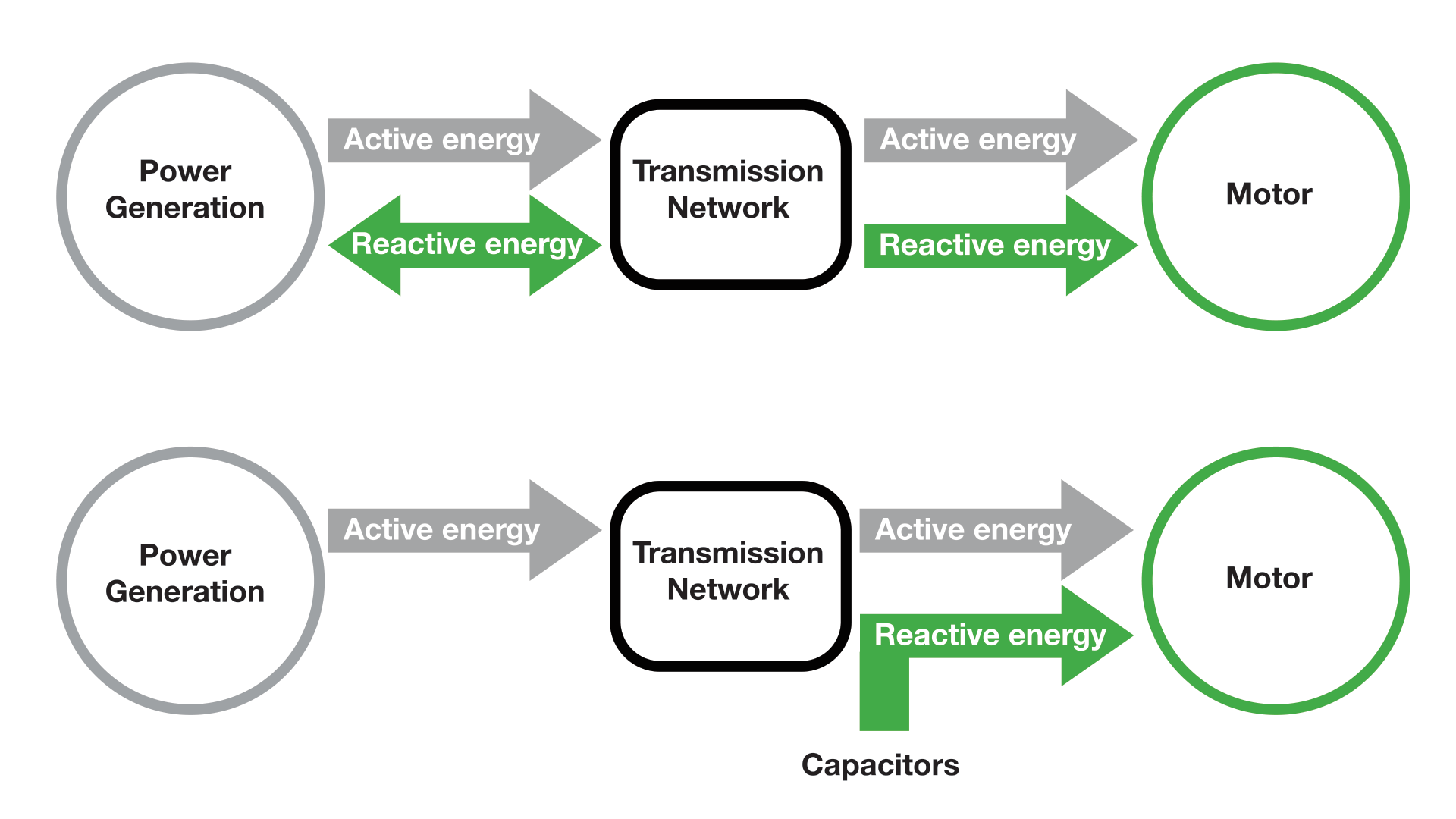
This is done with the addition of capacitors to the electrical network. It will compensate for the reactive power demand of the inductive load, thus reducing the burden on the supply. It also has no effect on the operation of the equipment. These capacitors draw current, and that leads the voltage, producing a leading power factor. If a capacitor is connected to a circuit that has a nominally lagging power factor, the extent the circuit lags is reduced proportionally. The corrected power factor is in the range of 0.92 to 0.95.
The below diagram depicts the flow of power to a motor, with and without the inclusion of Capacitor Banks.
How to Improve Power Factor?
The addition of capacitors connected in parallel with motors or lighting circuits can be done at the equipment distribution board, or at the origin of the installation. These capacitors act as reactive current generators. This reduces the total amount of current your system must draw from the utility. In theory, capacitors can provide 100% of the reactive power required, but in practice a power factor correction to approximately 95% is sufficient for maximum benefit.
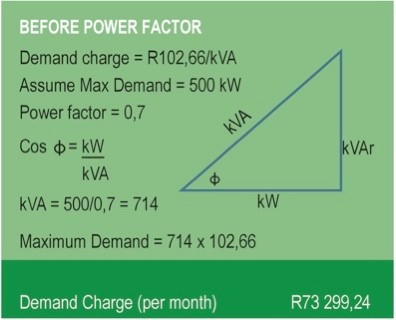
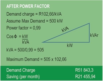
The figures above depict the before and after effects of power factor correction respectfully, on a power triangle for a specific load (Taken from the eThekwini Tariff Booklet 2020-2021).
As seen in the before picture, the power factor is 0.7 and the demand charge for the load was R73 299.24 per month. When the power factor is improved to 0.99 as a result of the addition of capacitor banks, it can be seen that the demand charge for the load was reduced to R51 843.30 and this represents a saving of R21 455.94 per month.
Power factor correction that is applied at the origin of the installation consists of a controller monitoring the VAR’s and performs the function of switching the capacitor in or out to maintain the power factor above the pre-set limit. Static power correction can be applied to each motor by connecting the correction capacitors to the motor starter. The two disadvantages of static power factor correction is that it can result in over or under correction and it cannot be connected at the output of various control equipment as it can damage the electronic components.
Have any questions on power factor correction?
Interested in adding power capacitors to your plant or upgrading the existing installation?
CHAT to our team of experts now!