
We’re unpacking transformers in our NEW series. An important discussion point is the protection of transformers. In this article, we give an overview of protection schemes specifically for oil-type transformers. Catch-up on previous articles in the series:
Part 1: Understanding Transformers and how they work
Part 2: Advantages, disadvantages and types of 3-Phase Transformers
Part 3: Protection Schemes for Oil Type Transformers
Understanding Transformer Protection
Transformer protection is vital in ensuring continuity of your electrical supply, safety as well as preventing damage to the electrical infrastructure in a system or network. Transformer protection schemes are installed in transformers to measure currents, detect faults and issue trip signals to circuit breakers to isolate a fault in an unprotected zone.
Stresses on a Transformer that are generated by a Supply
A transformer can be stressed by two types of over voltages that may damage or even destroy the transformer. These are:
- A lightning over voltage that may occur by a lightning strike falling on or near an overhead line that supplies the installation where the transformer is installed
- A switching over voltage that is generated from the opening of a circuit breaker or a load break switch
It is important that over-voltage protection is considered for:
- The bushings and insulation on the medium voltage side
- The neutral of the transformer (Star point)
- The bushing and lines on the low voltage side
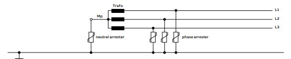
Protection must be provided against these two types of over voltages, and must be done with the use of Metal Oxide (MO) surge arrestors that are installed on both primary and secondary sides of the transformer. The surge arresters are required to be installed as close as possible to the bushings. An example of the positioning of surge arrestors for a star connected medium voltage transformer can be seen in the figure below.
Stresses on a Transformer that Result from Overload
An increase in the power demand from an installation will cause the transformer supplying it to experience an overload. This increase in demand can either be a result of the progressive increase in load or the addition of new loads to the installation itself. An overload will result in the temperature of the oil and windings increasing in the transformer, with a subsequent reduction in the transformer lifespan.
Thermal overload relays are implemented to protect transformers against overload faults. These relays provide protection by simulating the temperature of the transformer winding. The simulation is based on the current measurement and the thermal time constant of the transformer. This relay can also determine the remaining time before the emission of the tripping order and the time delay before re-energizing the transformer. Oil type transformers are also installed with thermostats that control the temperature of the oil.
The thermal overload relay, thermostat or heat sensor generally provides two levels of detection which are:
- A low level signal which is used to alert maintenance staff and isolate the faulted zone in the network
- A high level signal which is used to de-energize the transformer by issuing a signal to the nearest circuit breaker to isolate the faulted zone
TIP: Schneider Electric has the Easergy, Micom and Sepam series of protection relays that can be used in transformer protection schemes. CHAT to us for more information.
Overheating Protection
A transformer will overheat when experiencing overloads or short circuit conditions. The allowable overload experienced and the duration of it are both dependent on the transformer type and class of insulation that is used for the transformer.
Transformers can carry higher loads for a short period of time and if it operates for a very long period, damage to the insulation can occur as the temperature rises above an assumed maximum temperature. An oil-cooled transformer is said to be at maximum when the temperature is equal to 95°C. If the operating temperature of the transformer is greater than the specified insulated rating, this will then decrease the life expectancy of the transformer and cause breakdown to the insulation over a period of time.
Temperature control
Large transformers have winding temperature detection devices that are used to measure and monitor temperature parameters in the windings or winding temperature. The two methods of measurement are hot spot measurement and the second is referred to as the top-oil measurement. A temperature control box can be seen below which consists of a thermometer that is used to measure the temperature of a liquid insulated transformer.
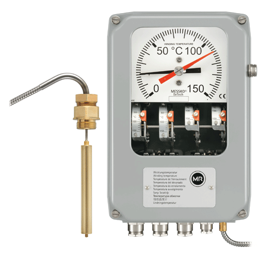
As seen in the figure above, the temperature control box consists of a dial gauge that indicates the temperature of the transformer by using the black needle, whilst the red needle is used to set the alarm point. If the black needle surpasses the red needle, then the device will activate an alarm. The high temperature which develops in the core and windings is referred to as the top oil temperature, and it gives an estimate of the hot spot temperature in the core. Currently, overheating protection is achieved using fibre optic cables that are installed within the low voltage winding to accurately measure the temperature of the transformer.
We continue our overview of protection schemes in the second instalment of this article. Watch this space for your complete guide to Understanding Transformers…
Need advice on how best to protect your transformer? CHAT to us now!