
Welcome to your comprehensive guide on Transformers. Before you get started on the final instalment, why not take a moment to catch up on all the articles in this interesting series:
Part 1: Understanding Transformers and how they work
Part 2: Advantages, disadvantages and types of 3-Phase Transformers
- Protection Schemes for Oil Type Transformers
- Protection Schemes for Oil Type Transformers continued
We’re wrapping up our series with a second instalment on Protection Schemes for Oil Type Transformers. In this article, we give a basic introduction to the Buchholz relay, its principle of operation, the advantages, and the limitations of having this vital piece of equipment installed on oil-type transformers. This articles also gives a brief explanation of the devices that are used to monitor the oil level and the temperature of the hottest part of the winding in your transformer.
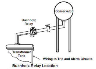
Buchholz Relay
A Buchholz relay is an oil and gas actuated protection relay that is implemented on oil immersed transformers. It is used for the protection of transformers from faults that occur inside it. Short circuit faults, inter-turn faults, incipient winding faults and core faults occur because of an impulse breakdown occurring on the insulating oil or deterioration in the transformer oil itself. The Buchholz relay will sense these faults, and issue a trip signal to the circuit breaker which is either on the HV or LV side of the transformer. This will then enable the circuit breaker to isolate the faulted zone.
Principle of Operation
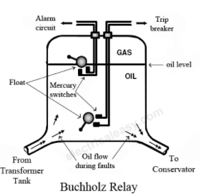
A fault that occurs in the transformer will cause the oil in the tank to become overheated, thus producing gas. The generation of the gas in the transformer is dependent on the intensity of the fault that occurred. As a result of this heat, oil in the tank will decompose, and this is used to detect winding faults. The gas then flows in an upward direction and gets collected in the Buchholz relay. This gas decomposes the oil in the Buchholz relay, and this displacement is equivalent to the volume of gas collected. The displacement of oil will result in the upper float closing the upper mercury switch that is connected to an alarm circuit. Therefore, when minor faults occur, the alarm gets activated. The amount of gas that is collected will indicate the severity of the fault. The lower float is unaffected by minor faults as there is not enough gas to move it.
A major fault, such as a phase to earth short circuit, will generate a vast amount of heat resulting in a large amount of gas being produced. This gas will also flow in an upward direction but the motion of it will be high enough to tilt the lower float in a Buchholz relay. In the event of a major fault, the lower float will cause the lower mercury switch to trip the transformer from the supply.
Advantages of a Buchholz Relay
- Indicates internal faults that may occur due to heating and helps avoid major faults
- Determines the severity of a fault without dismantling a transformer
- Isolates a transformer if a major fault occurs, thus preventing accidents
Limitations of the Buchholz Relay
- Only implemented in an oil immersed transformer
- Only detects a fault below the oil level
- Offers no protection for connecting cables, hence separate protection is needed for that
- High response time (the minimum operating time of the relay is 0.1 seconds)
Oil Level Monitoring Device
A transformer that has an oil conservator will often have an oil level monitor installed. This monitor has two contacts for an alarm. One contact is used for the maximum oil level alarm and the other contact is for the minimum oil level alarm.
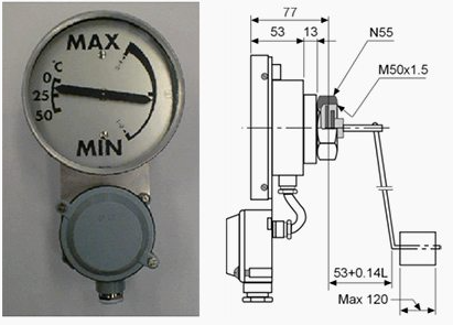
A top-oil thermometer consists of a liquid thermometer bulb that is in a pocket at the top of the transformer. The thermometer is used to measure the top-oil temperature of the transformer. This thermometer can have one to four contacts that sequentially close at successively higher temperatures.
Winding Thermometers
A winding thermometer is a device that responds to both the top-oil temperature and the heating effect of the load current. A winding thermometer leads to the creation of an image that depicts the hottest part of the winding. This top-oil temperature is measured by the procedure mentioned above, but this measurement is expanded with a current signal that is proportional to the loading current in the winding.
The current signal is taken from a current transformer that is installed in the bushing of that winding. A resistor element is fed with this current, causing it to heat up, thus heating up the measurement below and finally resulting in an increased indicator movement.
The temperature bias is directly proportional to the resistance of the electric heating (resistor) element. The bias should correspond to the difference between the hot-spot temperature and the top-oil temperature. The time constant of the heating of the pocket should equal the time constant of the heating of the winding. The temperature sensor will then measure a temperature that is equal to the winding temperature, if the bias is equal to the temperature difference and the constants are equal.
Need advice on your transformer? CHAT to us now!